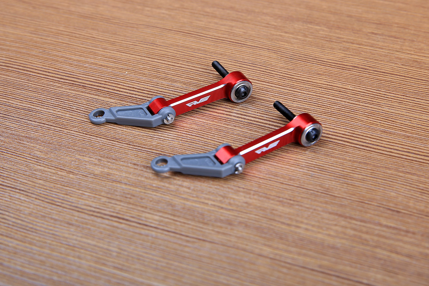
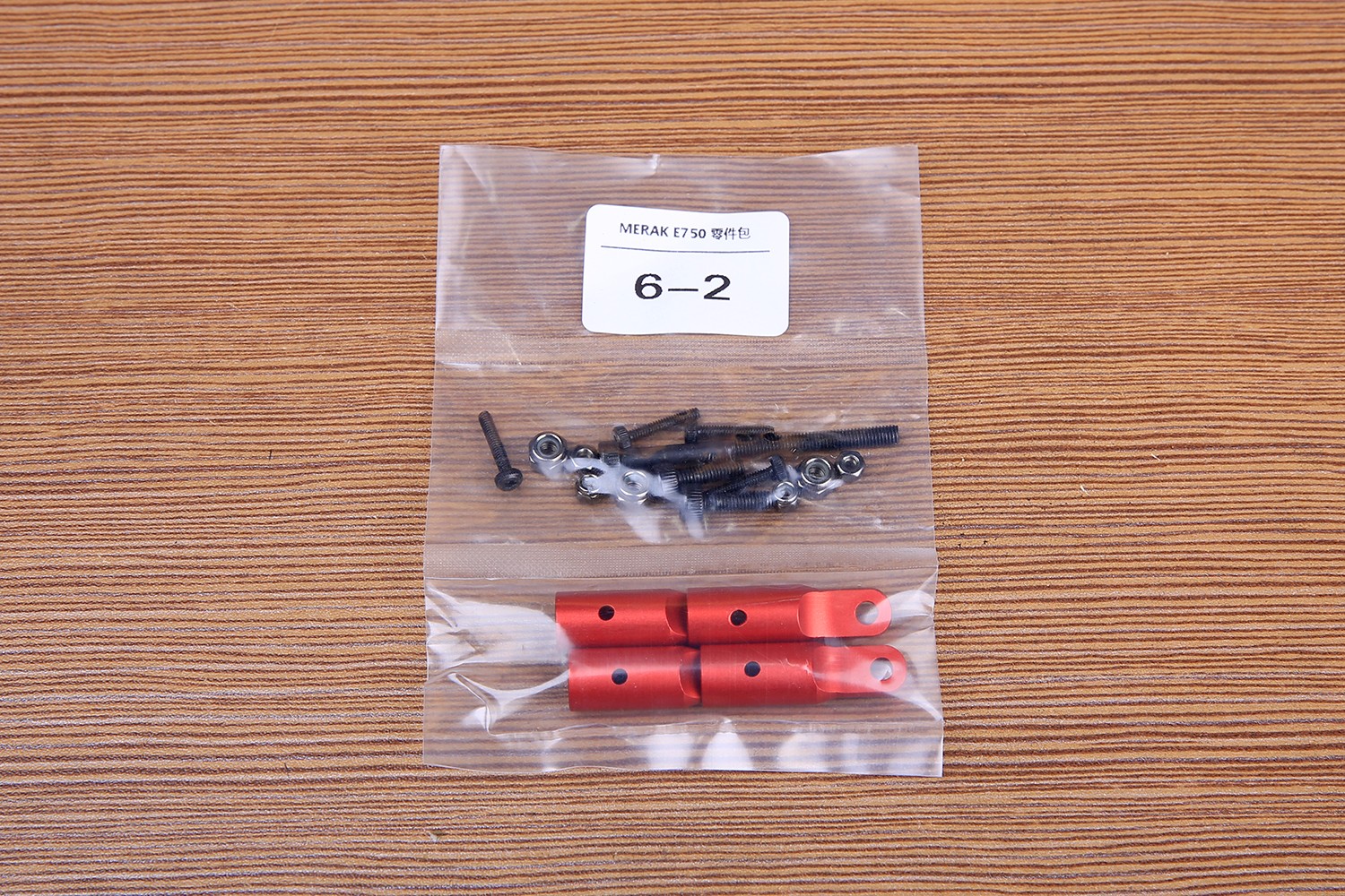
Next is the installation of the tail support, take out the 6-2 parts package. The carbon fiber tail is inside the package of the tail pipe.
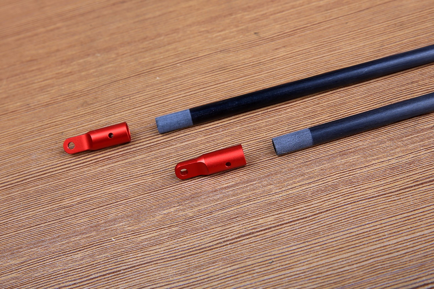
In order to increase the bonding strength, the tail carbon rods were processed in advance, and everyone saved the trouble of polishing them.
The tail support and tail support are fixed with AB glue or epoxy resin. If you still feel the strength is not assured, we also have a special fixing screw.
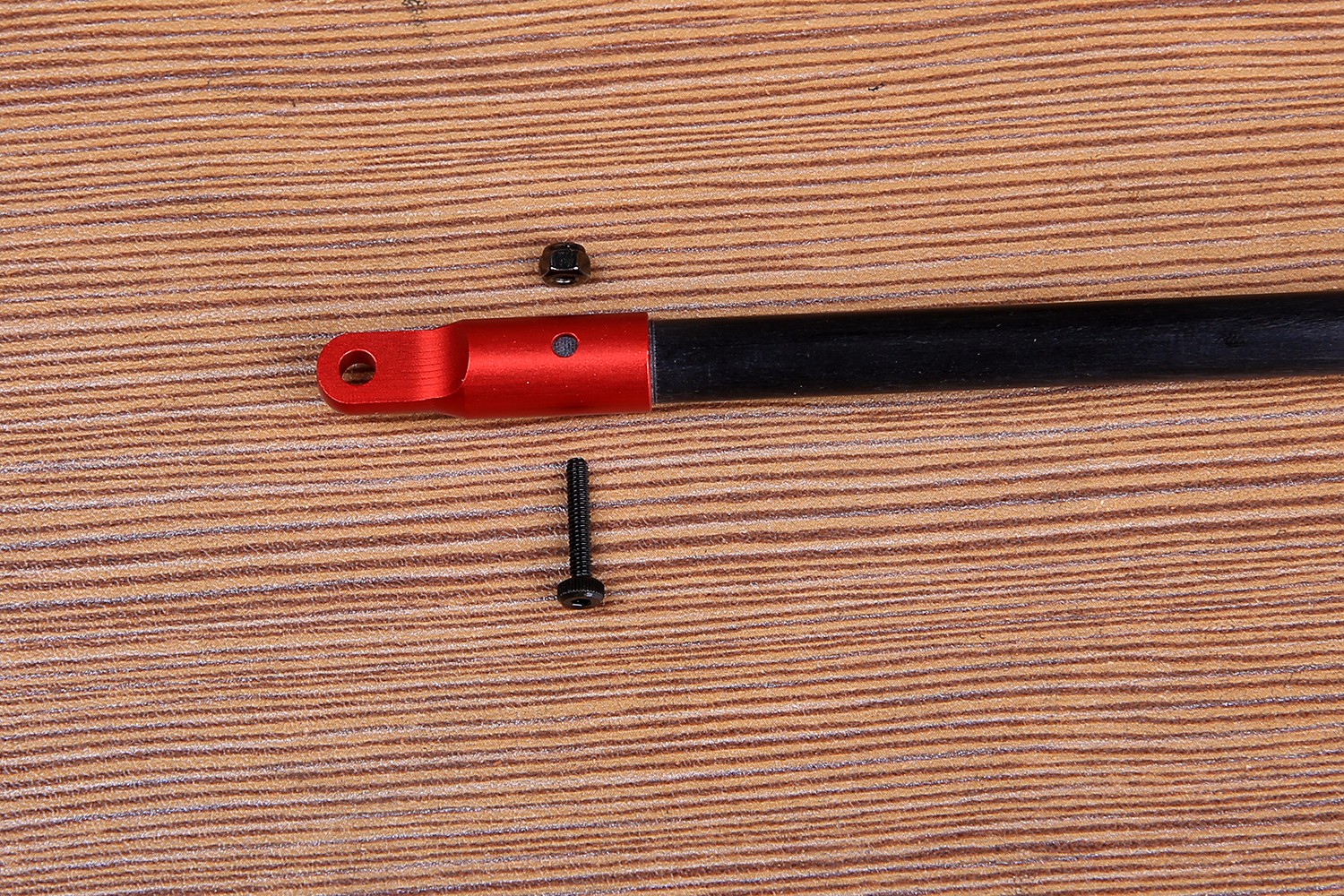
Below is the tail support head glued with AB.
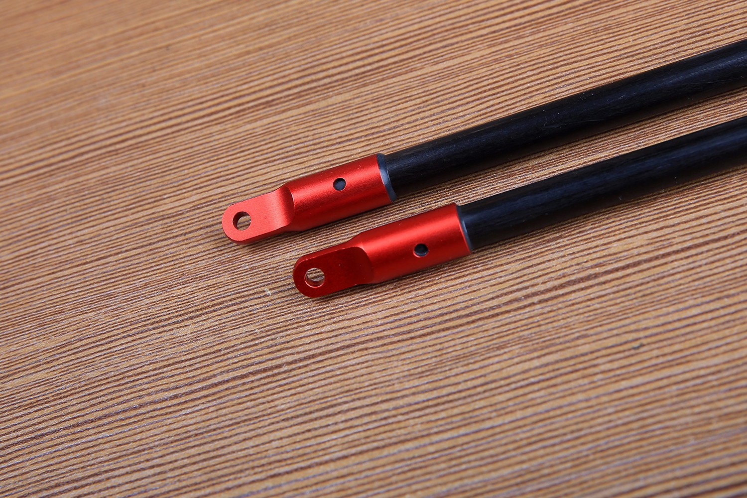
The tail support is fixed at this position of the side panel, as shown in the figure:
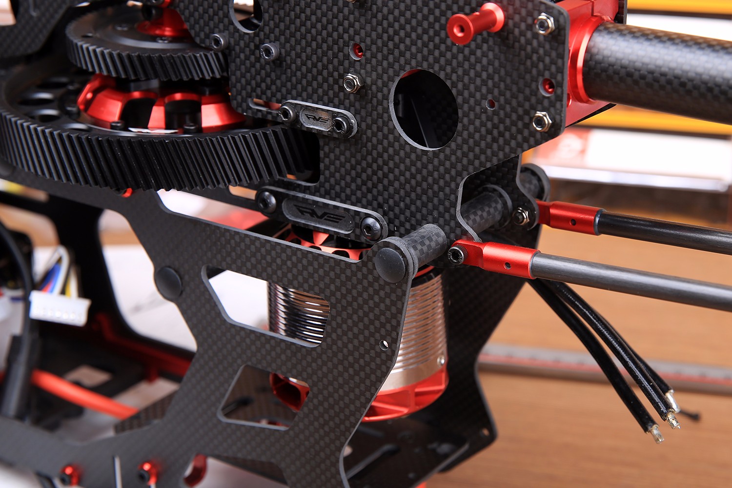
The rear part is fixed to the tail bracket by M3*40 hexagon socket screws.
The following parts packages are mainly the parts that are in the control part of the steering gear.
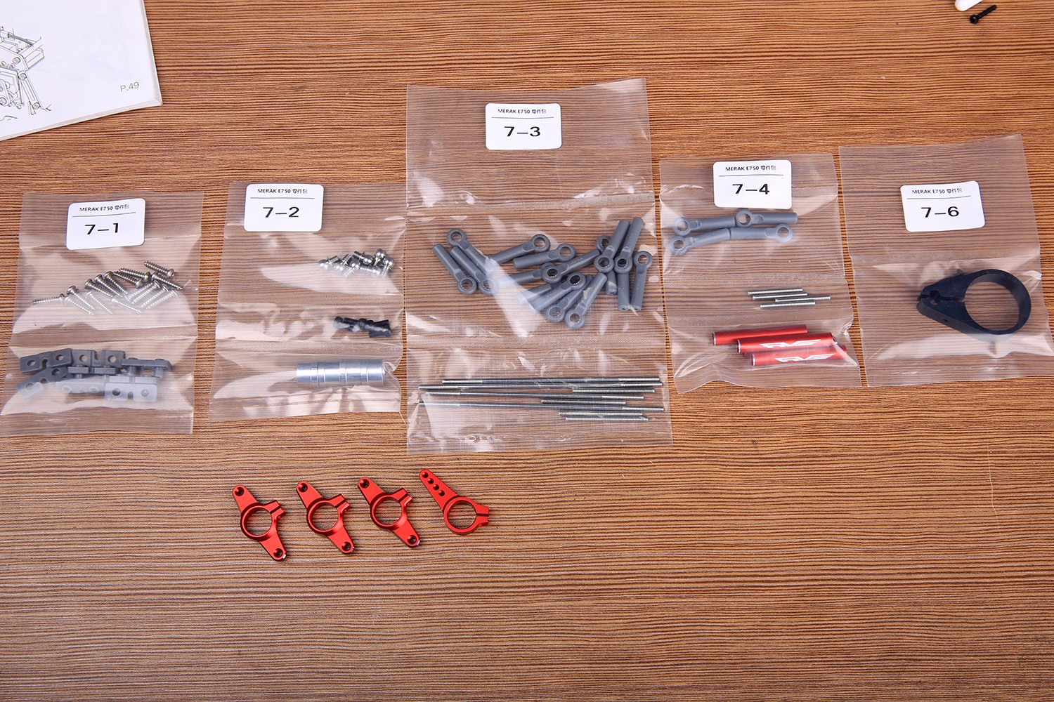
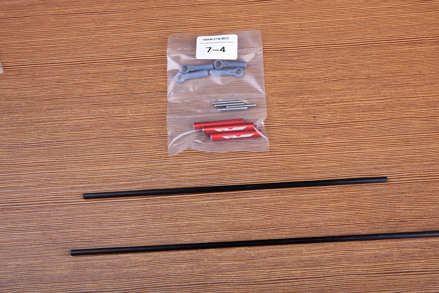
Let's first install the 7-4 tail rod parts package. The 4MM carbon rod is inside the tail tube package.
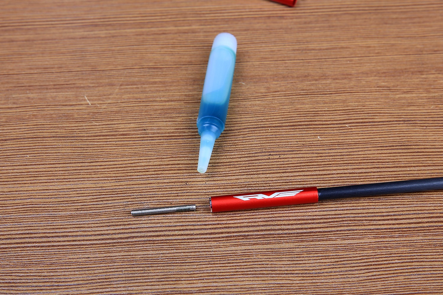
The screw is fixed to the aluminum sleeve with green screw glue.
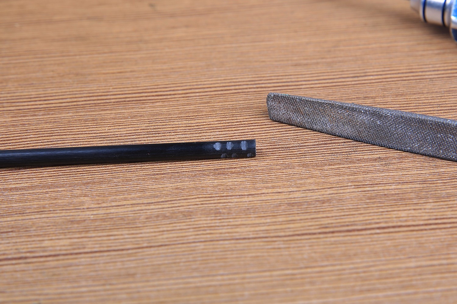
The aluminum sleeve is bonded to the carbon tube with AB glue. Note that the carbon tube uses a trowel to repair several grooves to make the bond strength higher.
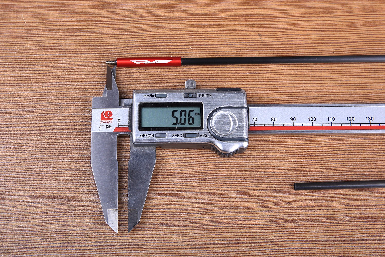
The length of the rod is about 5mm, and the screw is solidified and then screwed on the ball.
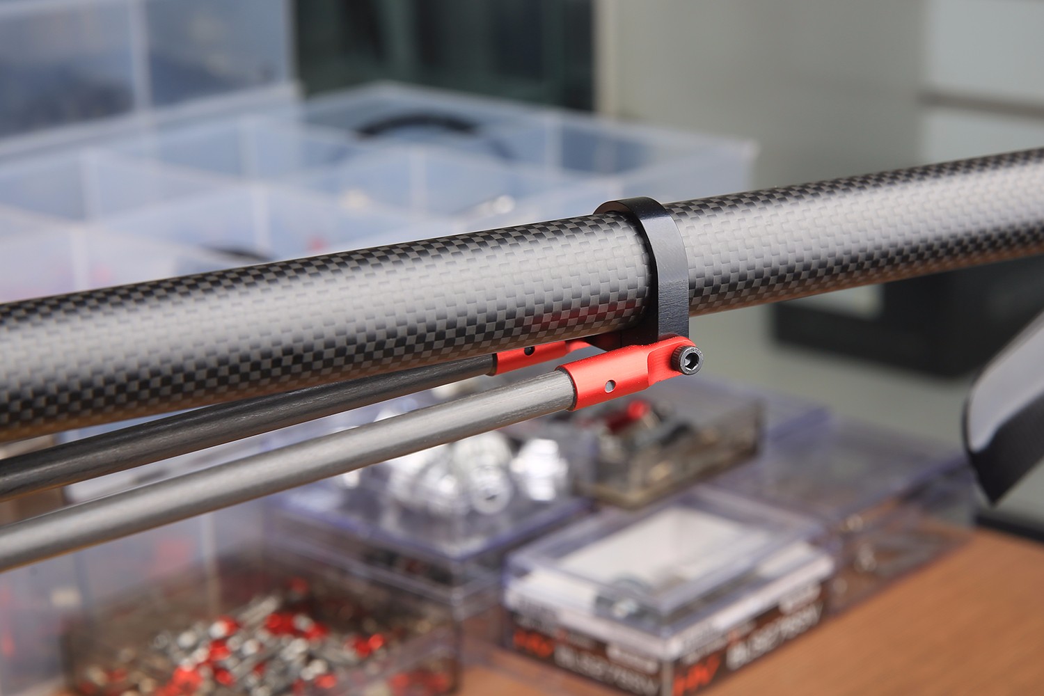
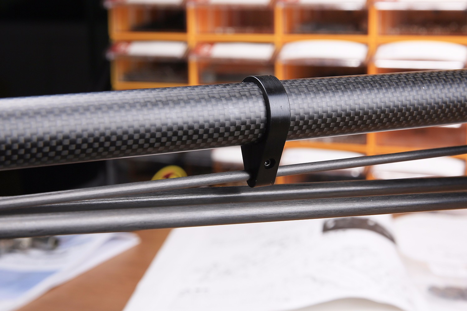
7-6 parts package, tail rod fixing ring.
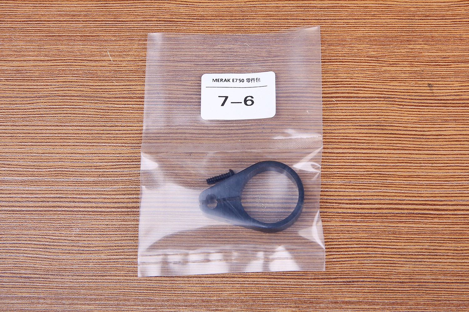
The position of this ring should not be selected in the middle of the tie rod, which is easy to cause resonance. It is appropriate to move forward or backward by about 2 cm. Be careful to ensure the linearity of the tail rod during installation.
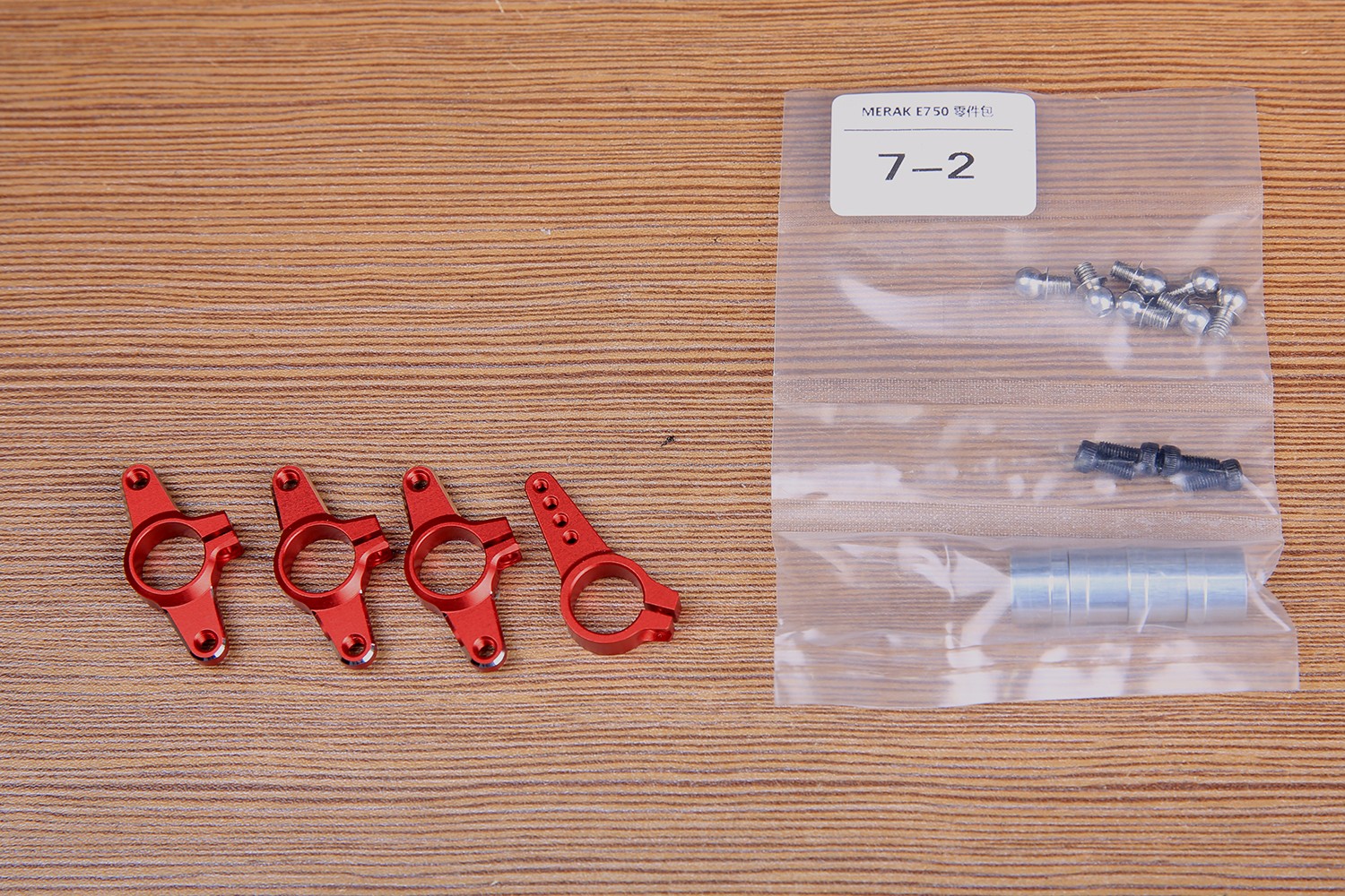
Below is the 7-2 parts package, the installation of the steering wheel.
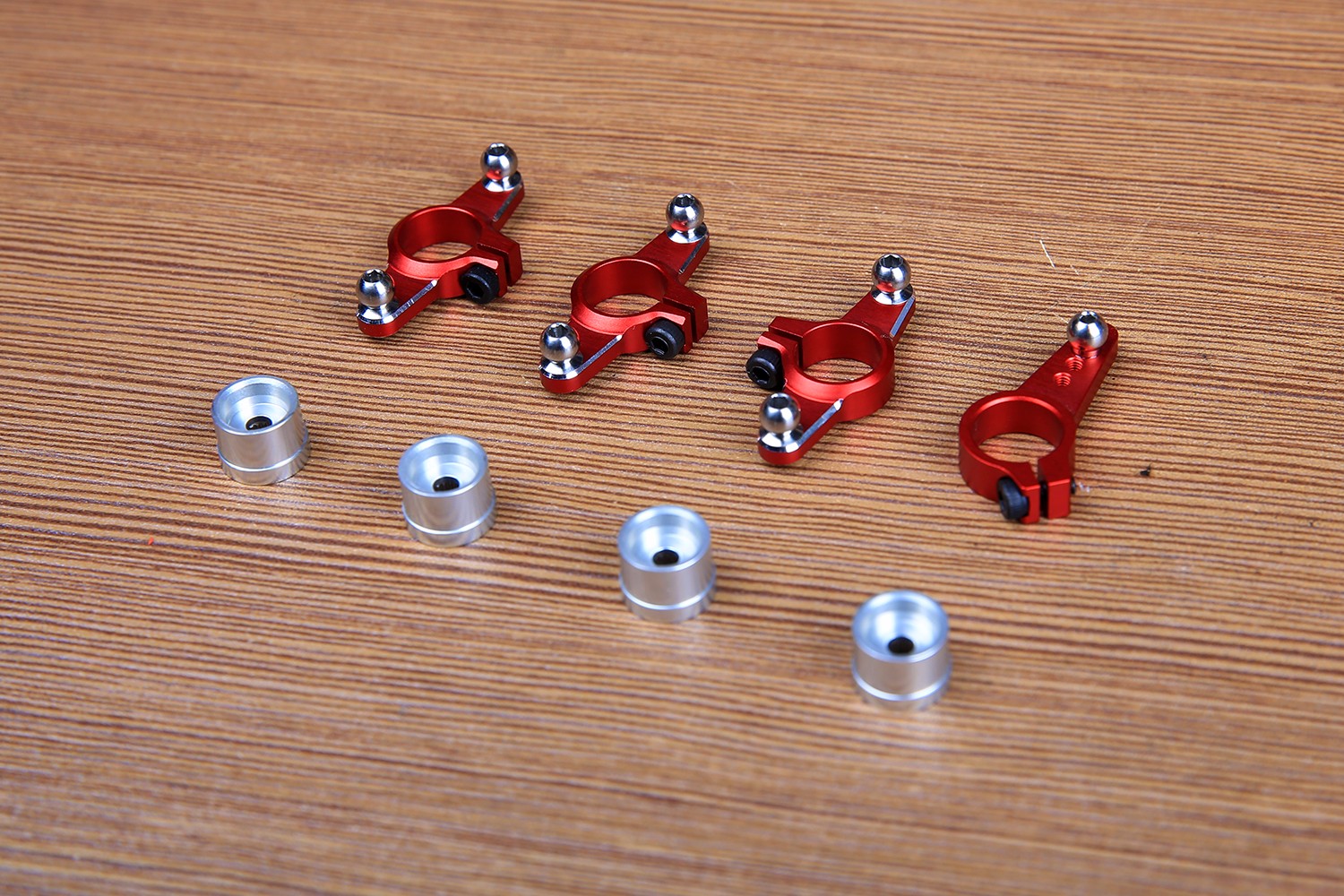
The ball head should be fastened with blue screw glue. Please install the ball head in the direction of installation as shown below.
Next, start the assembly of the rotor head section: Take out the parts box.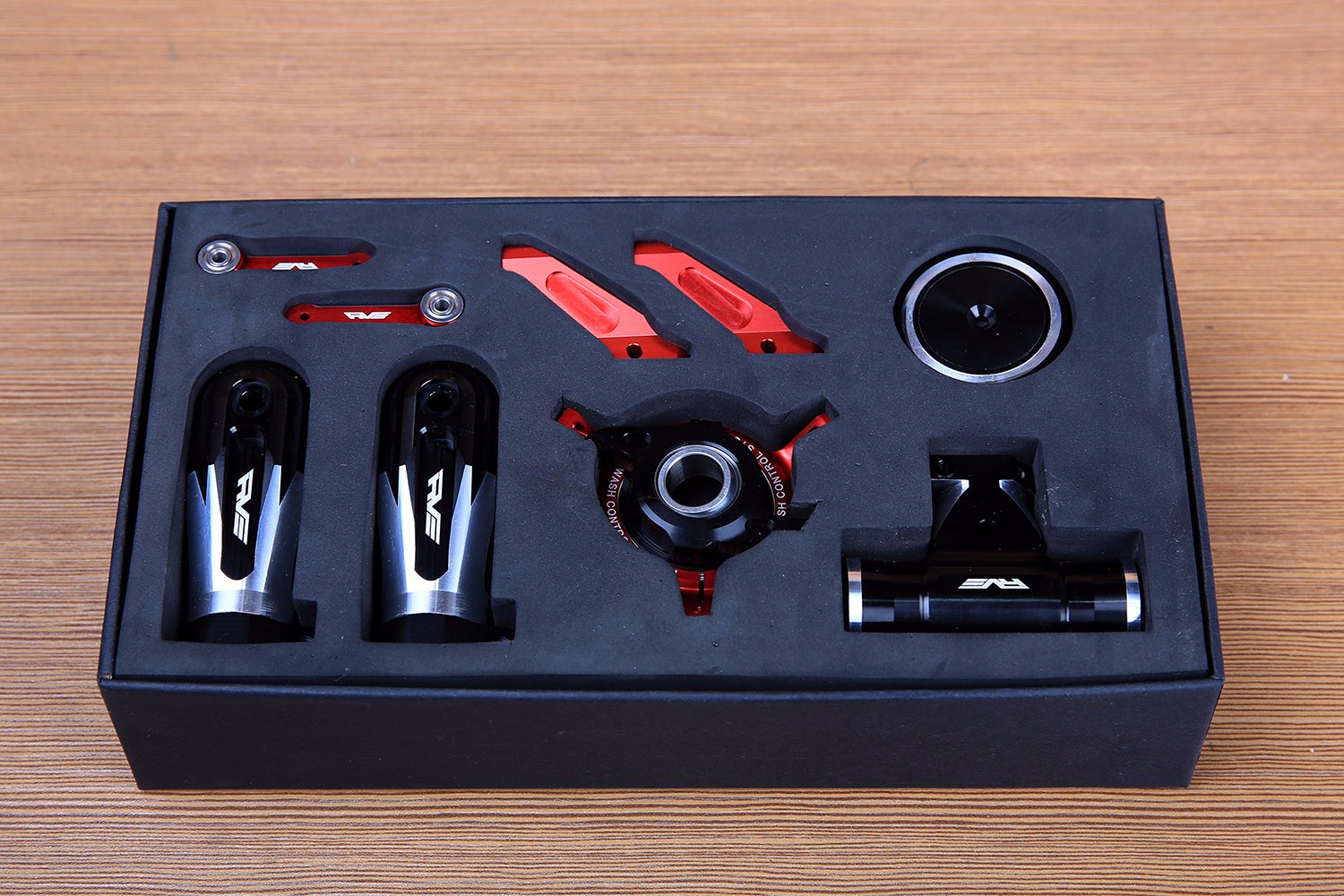
Screw package and accessories:
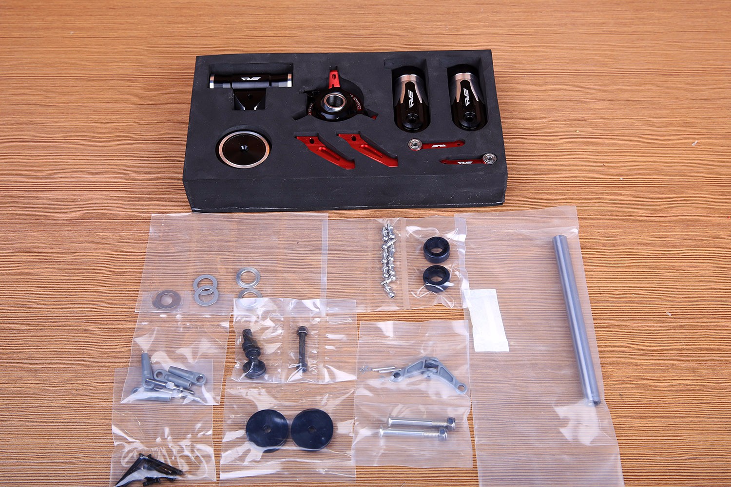
First assemble the swashplate, paying attention to the blue screw glue for each ball head.
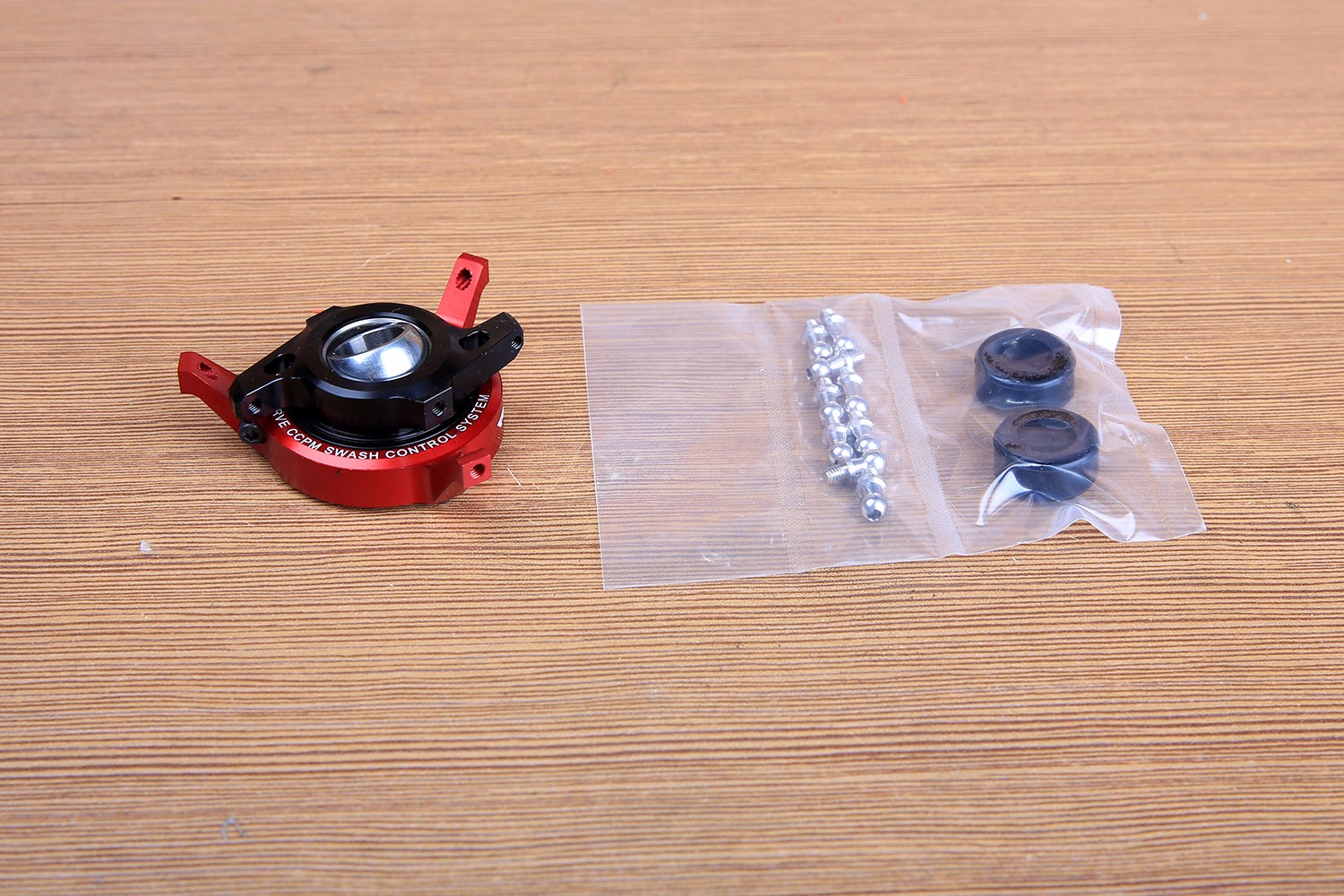
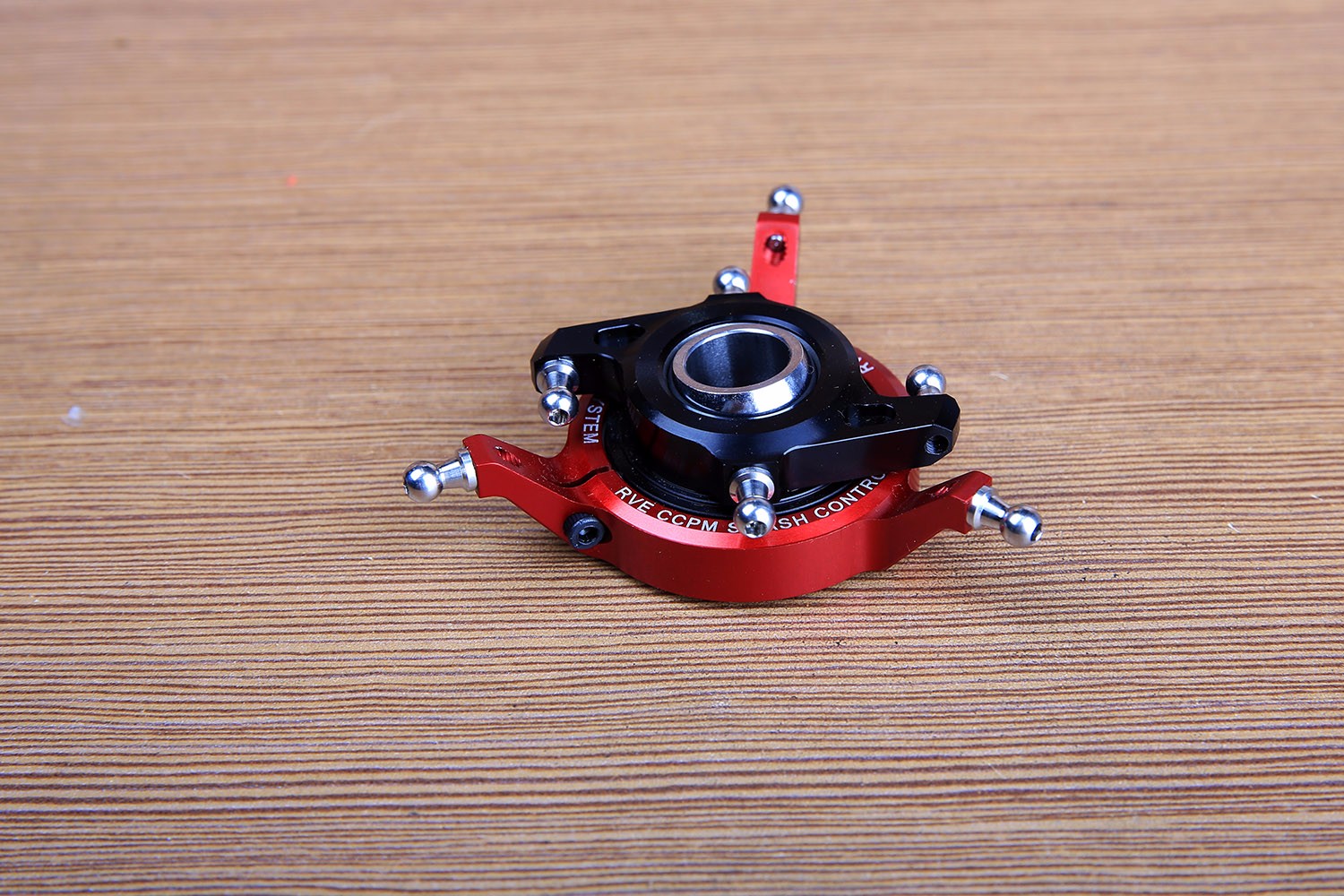
Start assembling the paddle after the swash plate is installed.
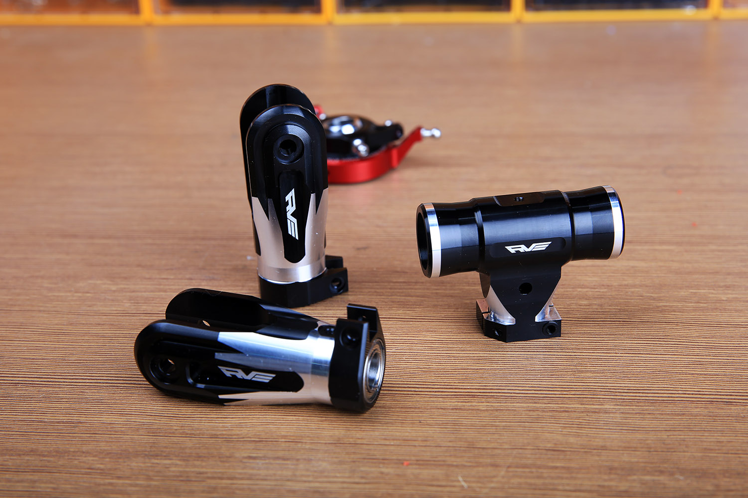
The paddle rocker arm is fixed first.
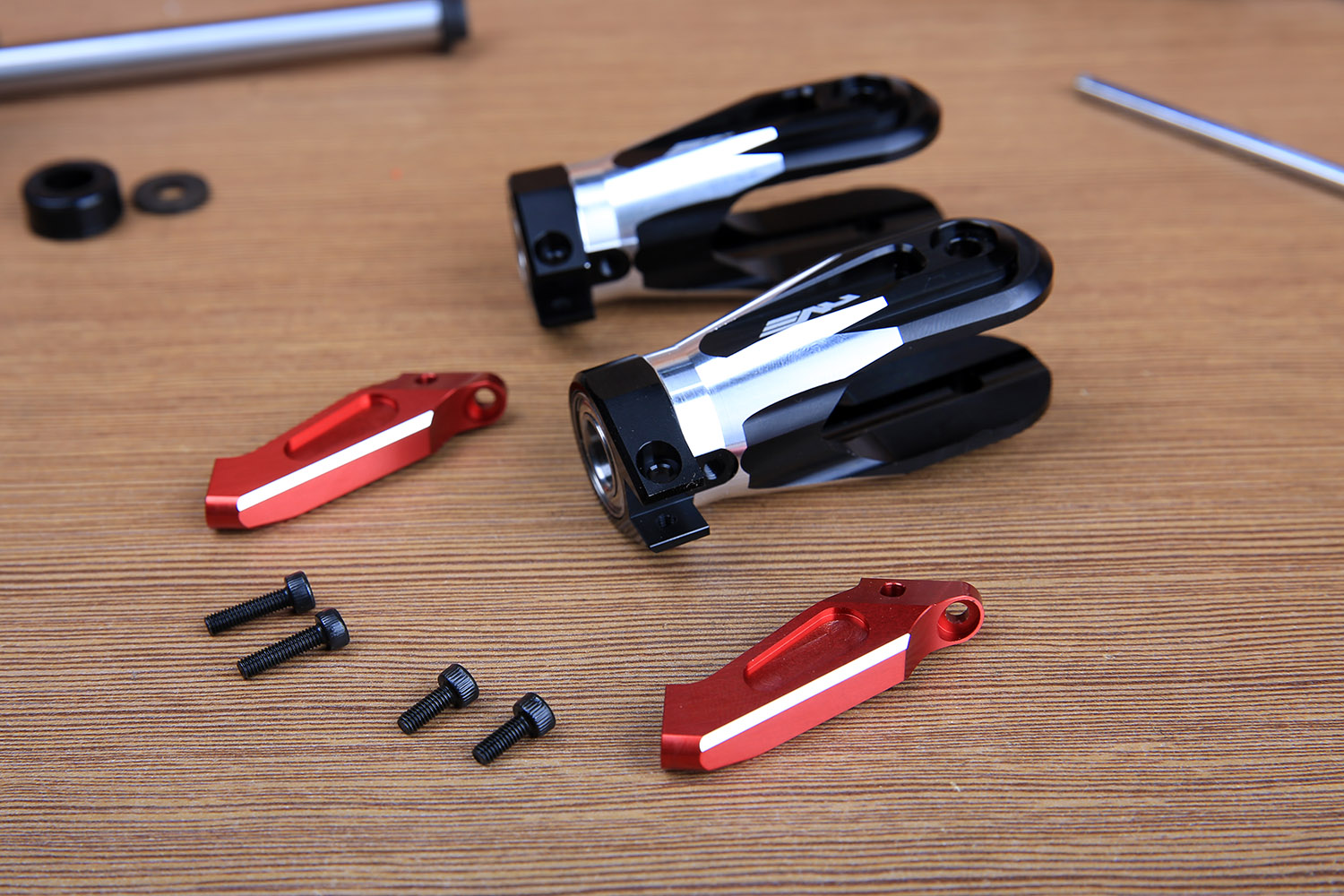
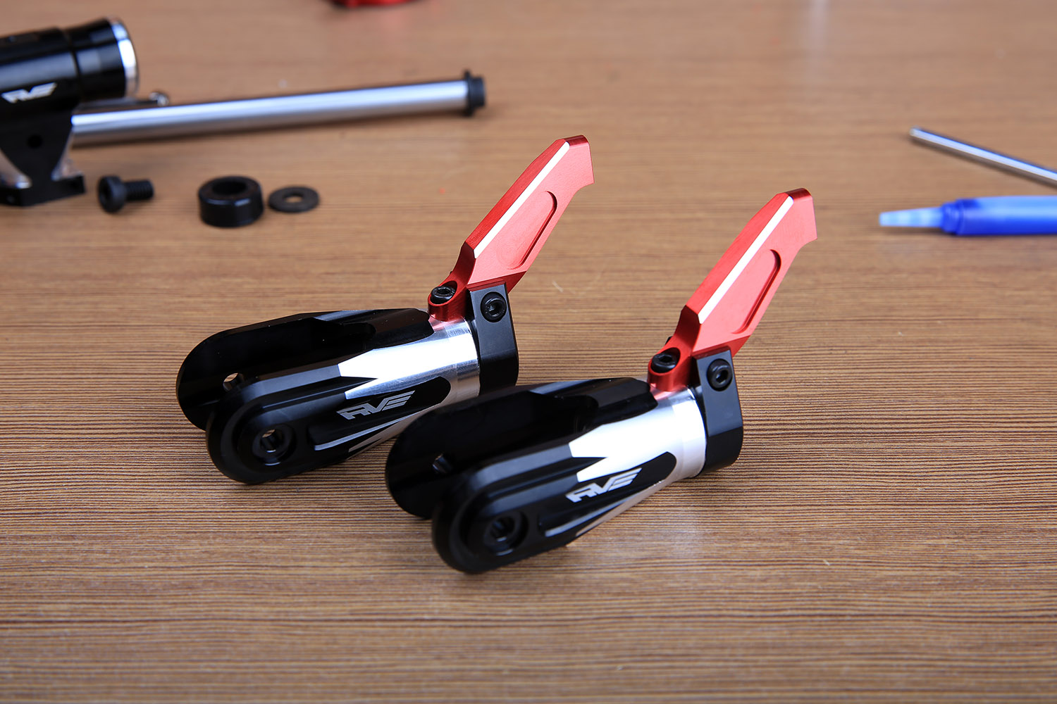
The ball is loaded into the outermost wire hole.
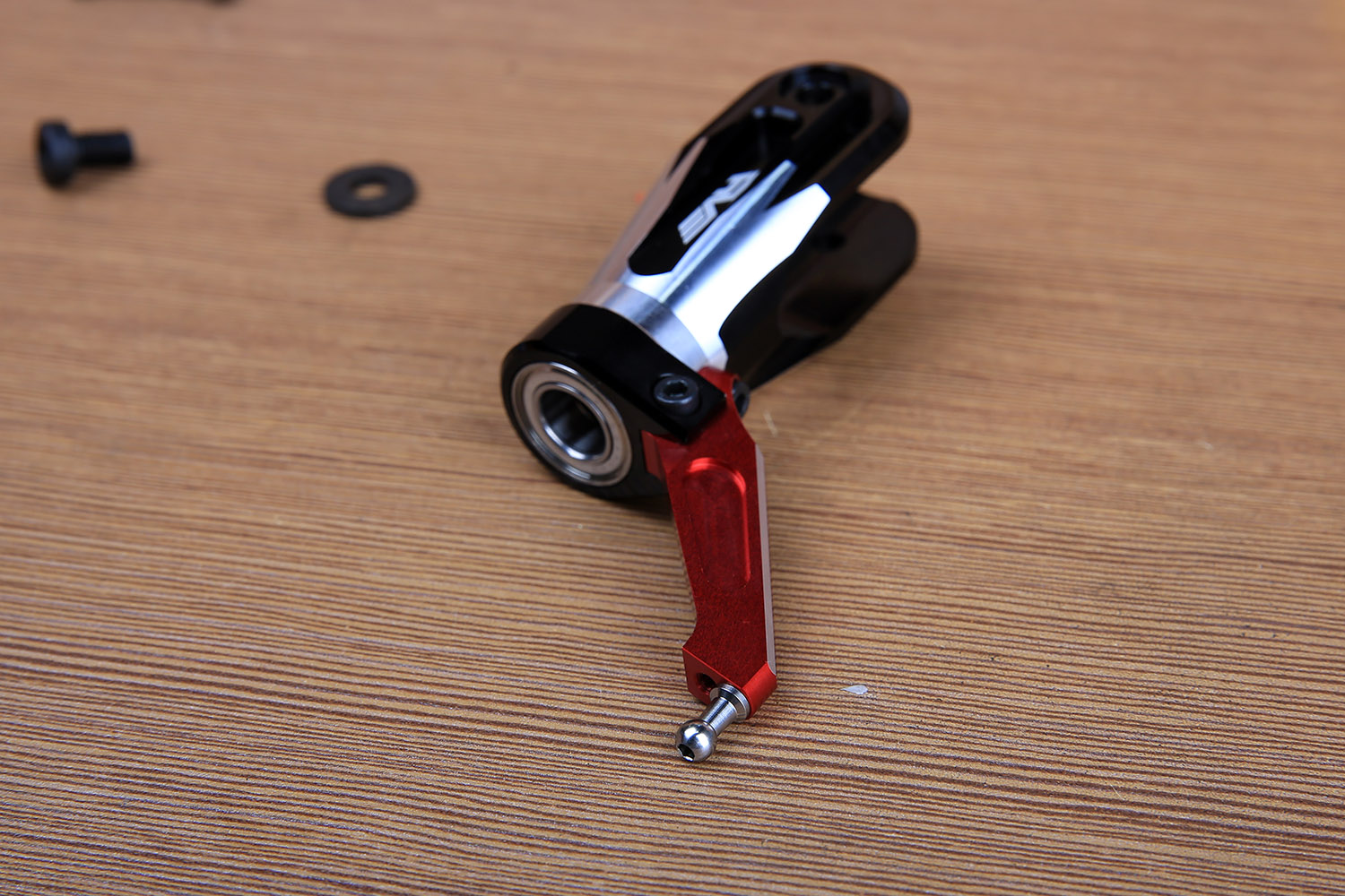
Take out the horizontal shaft screw package.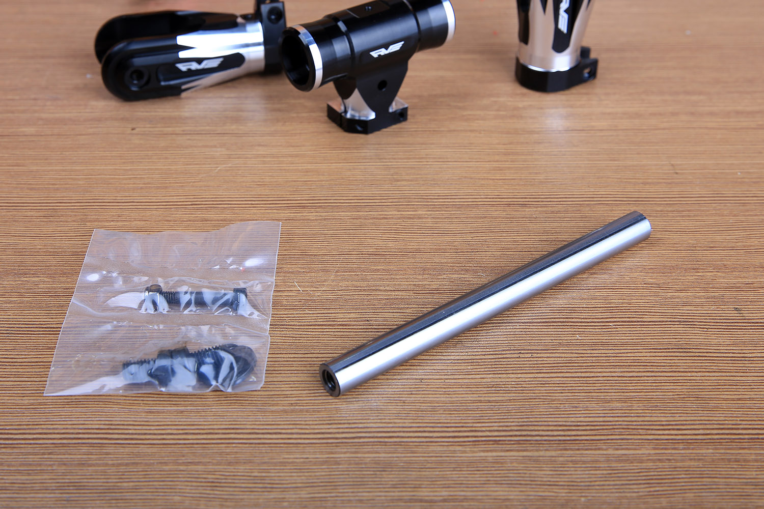
Need to use blue screw glue.
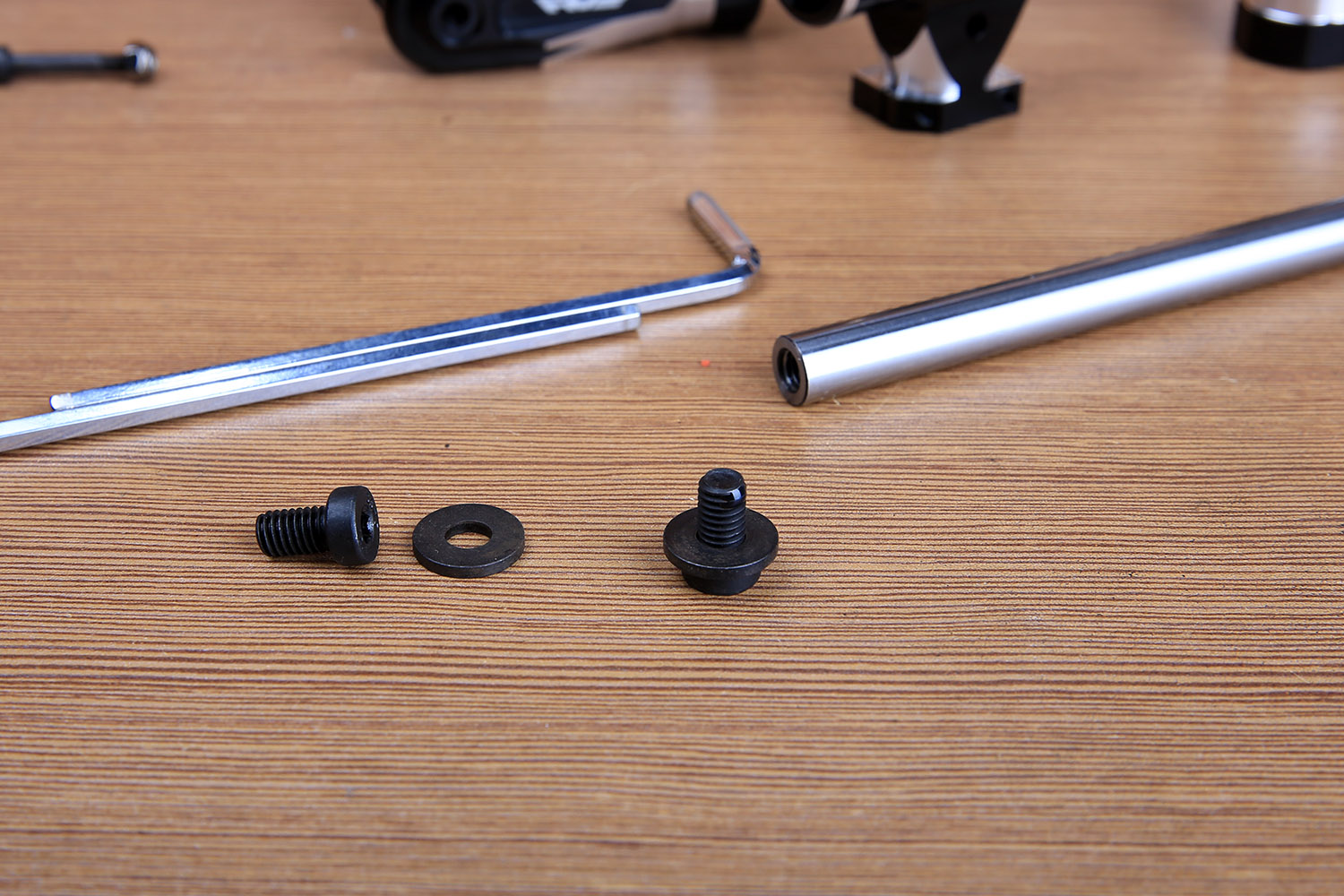
First tighten the screw on one side.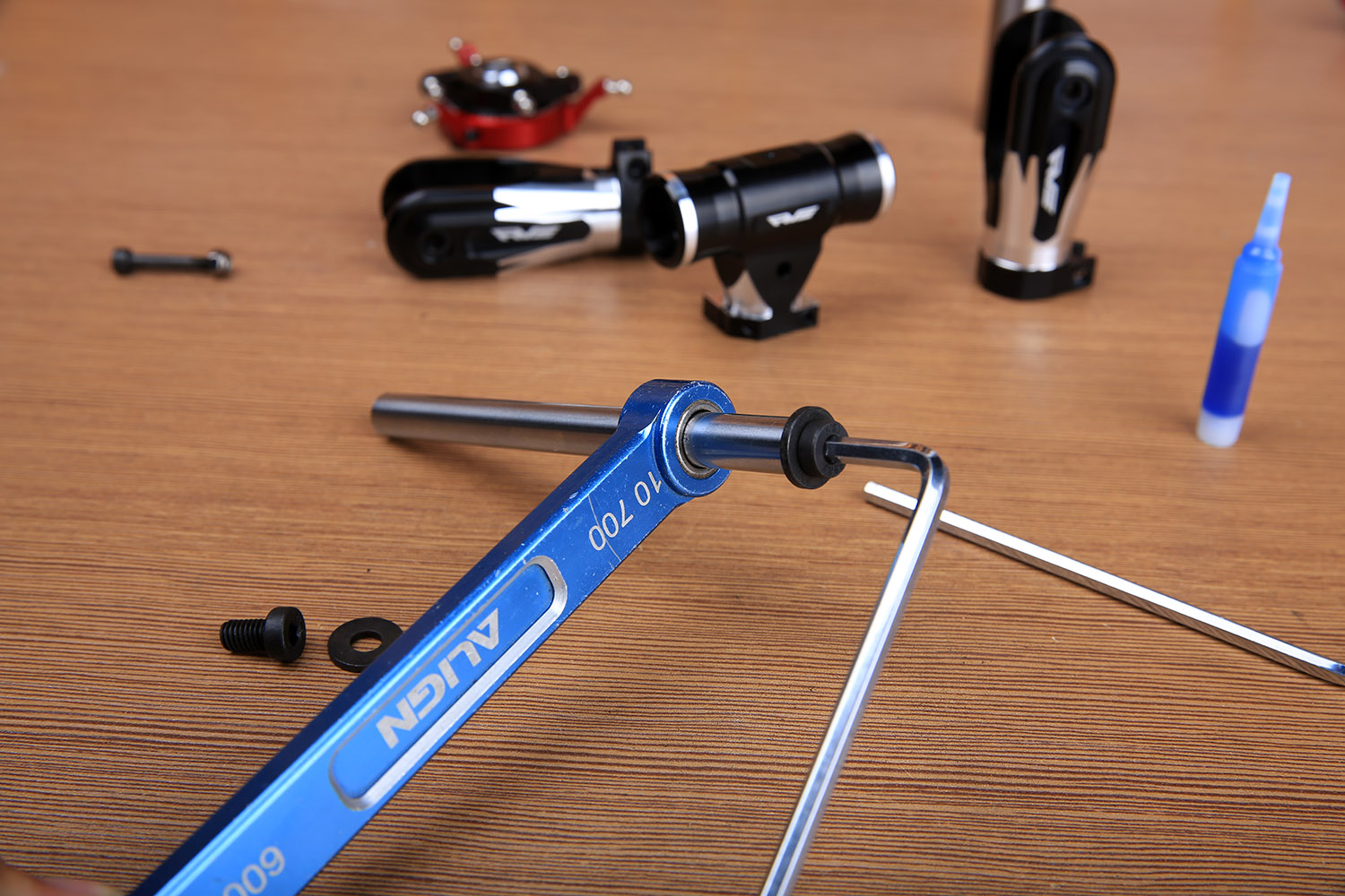
Horizontal axis apron with silicone grease.
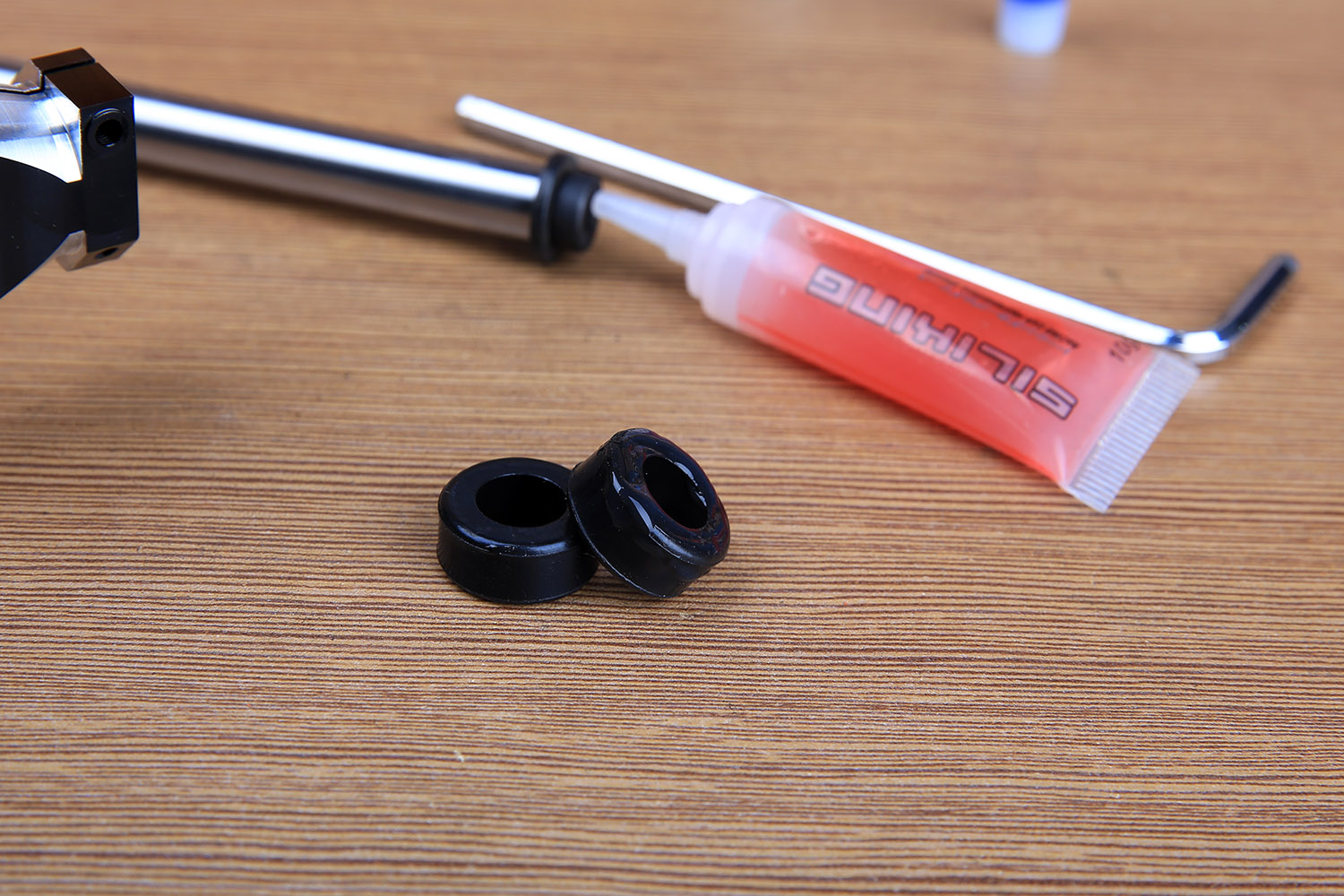
The bearings in the paddles have been installed, and the thrust bearings are also full of oil and do not need to be disassembled. The horizontal axis clearance adjustment gasket is provided with several different thicknesses. This gasket is mainly used to adjust the virtual position between the paddle clamp and the neutral joint. Try not to install the adjusting gasket first, if you need to add a gasket. Please note that the gap gasket is rubberized by the rotor head, and the outer gasket is also directional, with the step facing the paddle clamp.
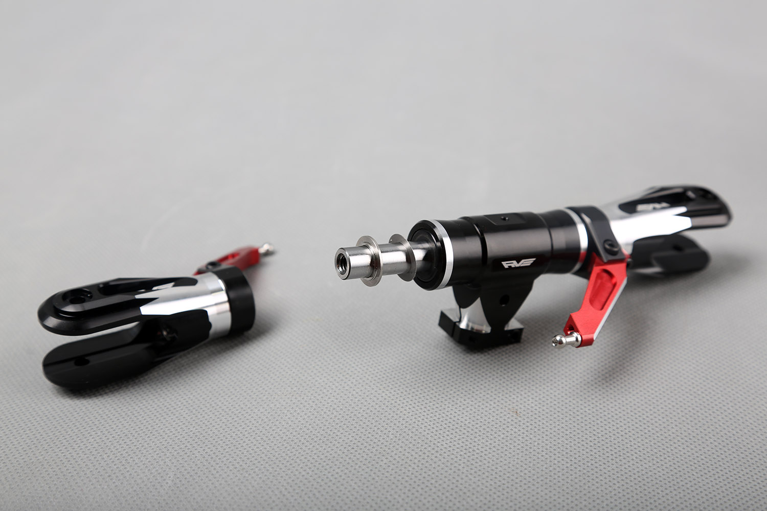
By the way, install the brake disc.
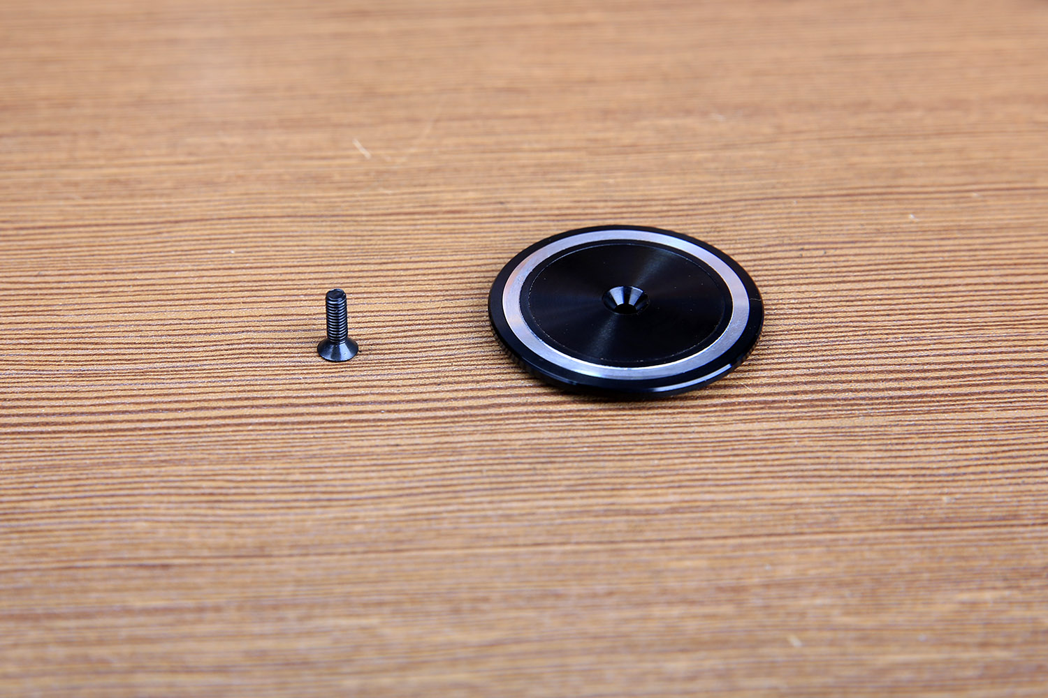
Note that the horizontal axis screw is recommended to be a little more screw, and the screw does not need to be tightened with great force.
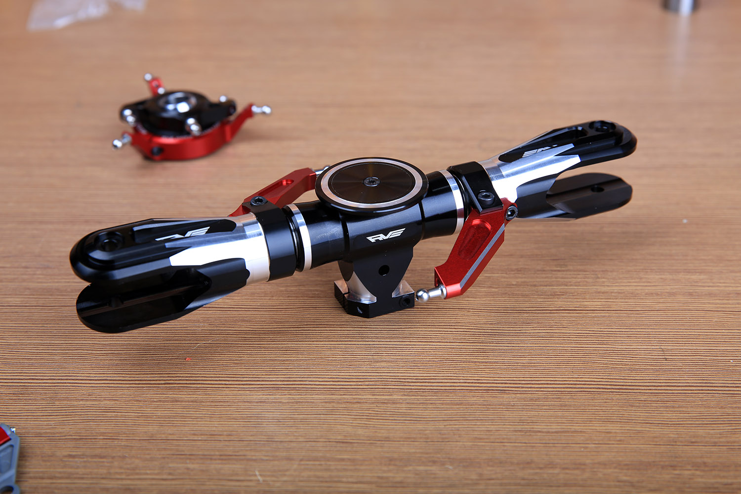
The swashplate is placed first into the spindle and the rotor head is mounted.
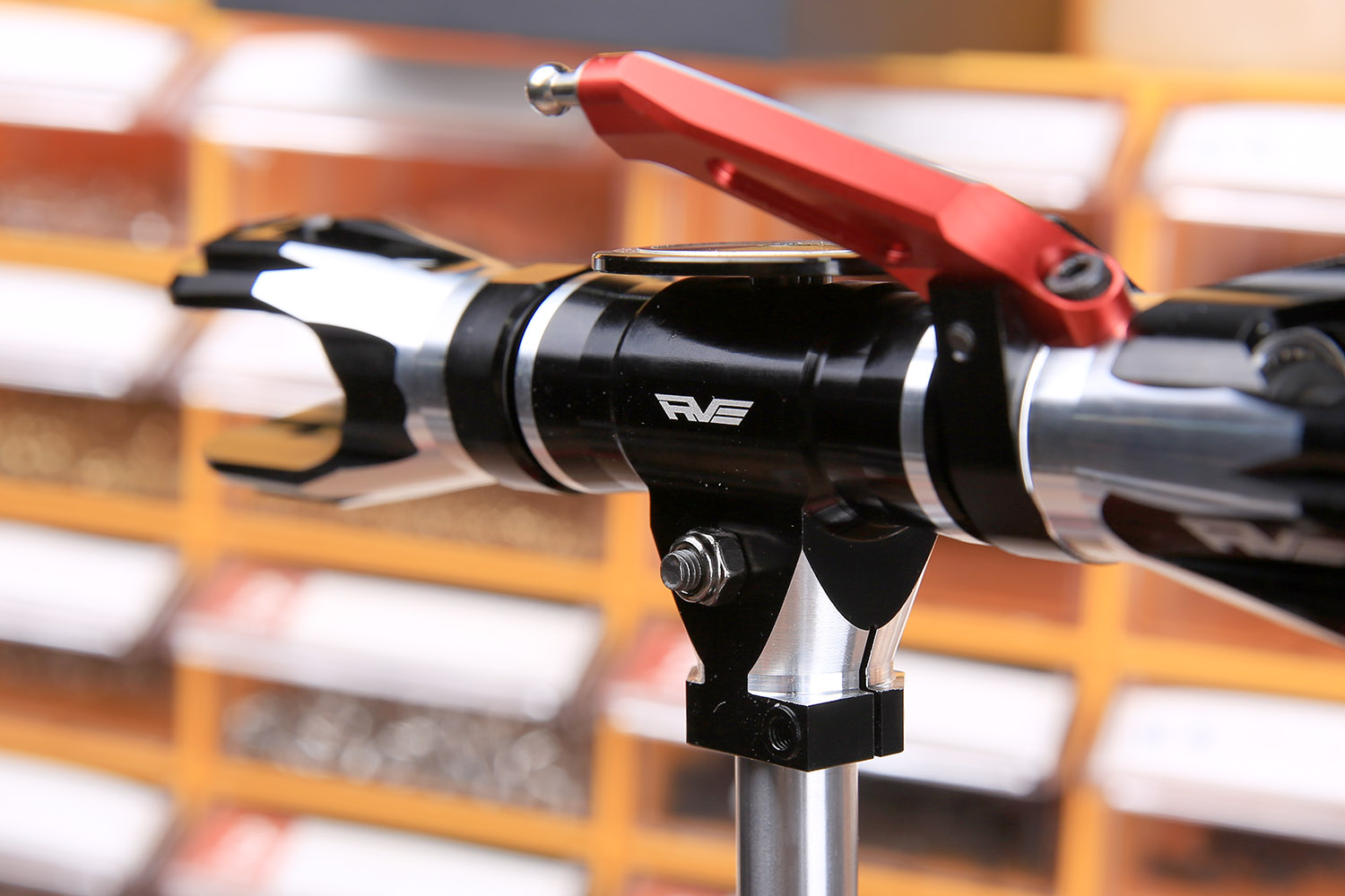
Next install the phase arm.
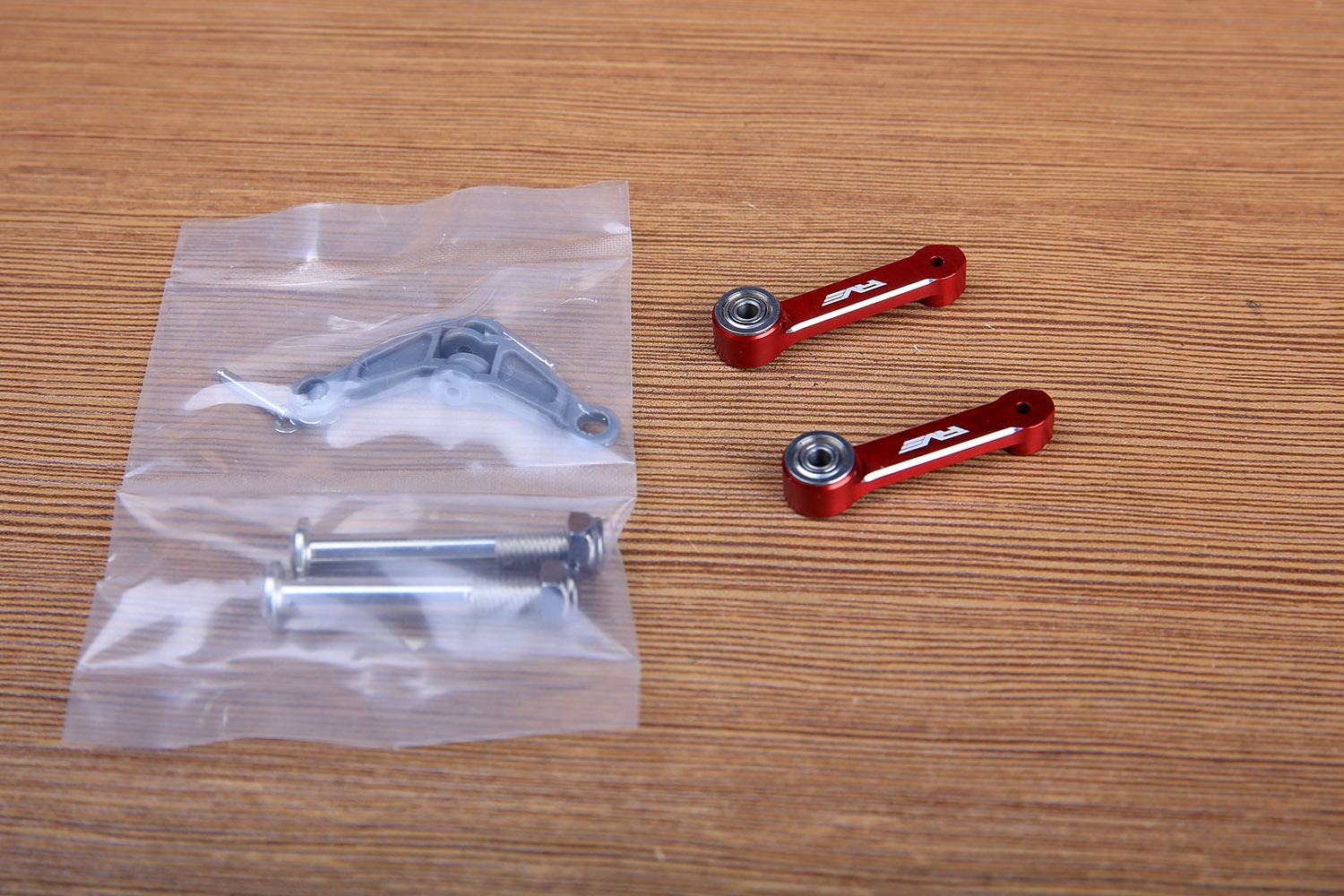
First attach the spring clip to the pin.
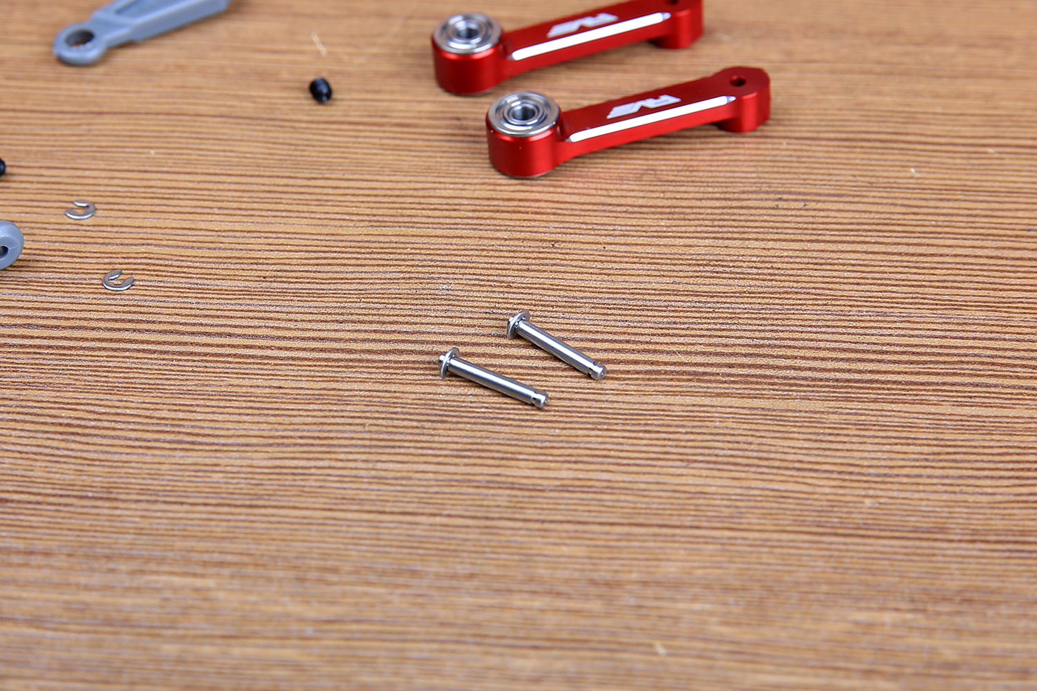
After the pin passes, the spring clip on the other side is attached. Please pay attention to the direction of the horn arm.
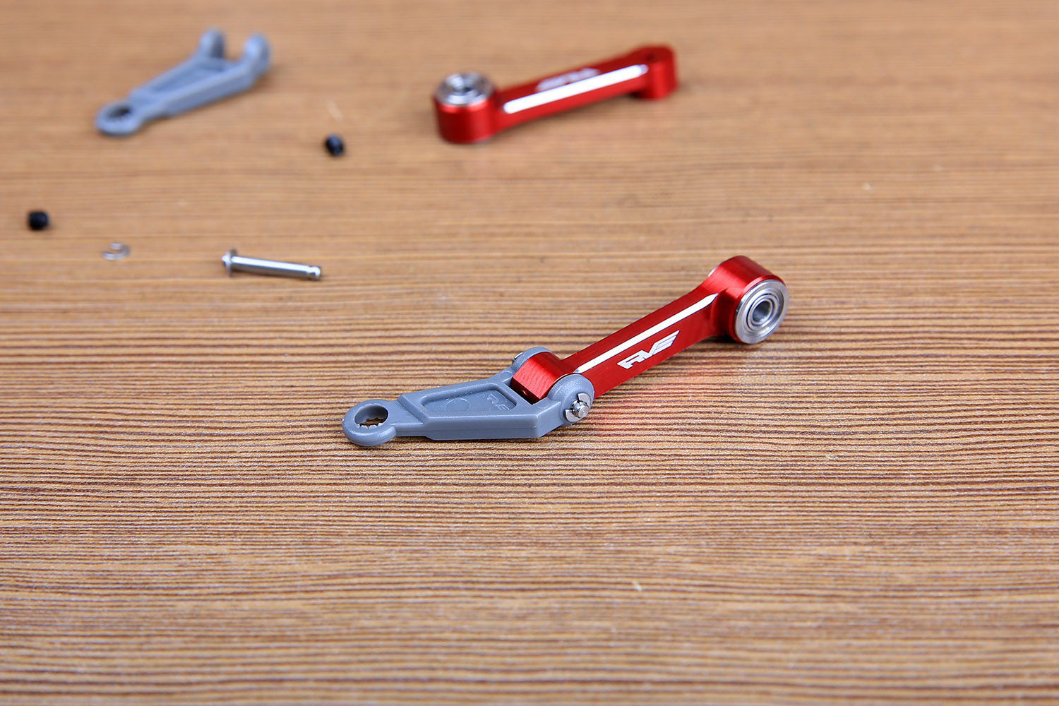
Finally the top wire is fixed.
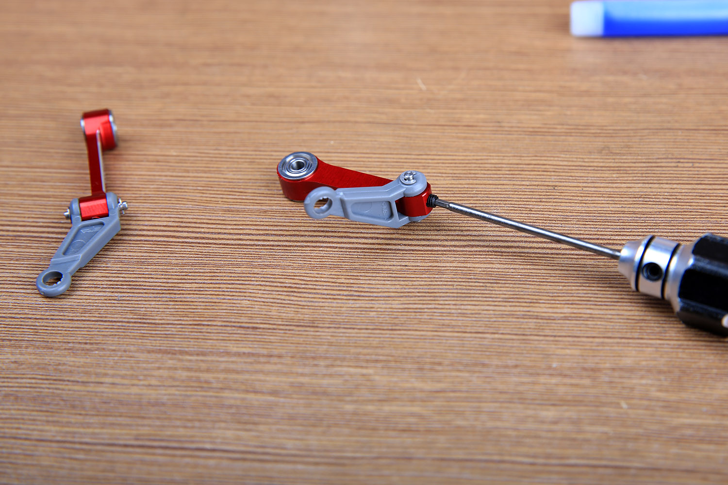
The screws are installed and installed on the center.
